Introduction
In our previous blogs, we’ve covered the aspects of the oscillator design with
Part I: The Crystal Oscillator Design Basics and
Part II: Best Practices for Crystal Oscillator Layout.
Now, when we have our prototypes manufactured, it’s time to test and verify all important aspects of our oscillator.
What do we need to verify in the oscillator design?
Once the design has been done and the prototypes are manufactured, it’s time to validate the oscillator design. The points that need to be validated are listed and analyzed in the following sections.
Frequency accuracy
The first step is to validate the frequency accuracy. This is done by measuring the actual frequency and modifying the load capacitors to trim the frequency to the exact desired (depending on available instruments, the accuracy of up to ±1 ppm is possible). What is important to note is that both the crystal and the load capacitors have their manufacturing tolerance, so this procedure needs to be conducted on at least 3 modules, preferably 10.
Depending on the oscillating frequency, the measurement setup will vary, however, the idea is the same – take your N (N being a number between 3 and 10) freshly manufactured prototypes and measure the oscillation frequency. If the frequency is too high, increase the load capacitors (for the sake of simplicity, keep their values equal). If the frequency is too low, decrease them.
The key is to find an optimal value of load capacitors so that all N prototypes have an oscillation frequency as close as possible to the ideal one (while using the same load capacitors). The greater the N number, the better. The reason for doing this on N modules is to eliminate the crystal manufacturing tolerance (i.e. initial frequency accuracy). Of course, the capacitors for this purpose should have a tight tolerance with C0G dielectric. The alternative to the measurement of N modules is to use the reference crystal. This is the crystal that you need to specifically order from the crystal manufacturer.
What is special about this crystal – the manufacturer validated that by using the exact rated load capacitance, this crystal will have exactly the nominal oscillation frequency. In other words, this crystal has zero initial frequency tolerance.
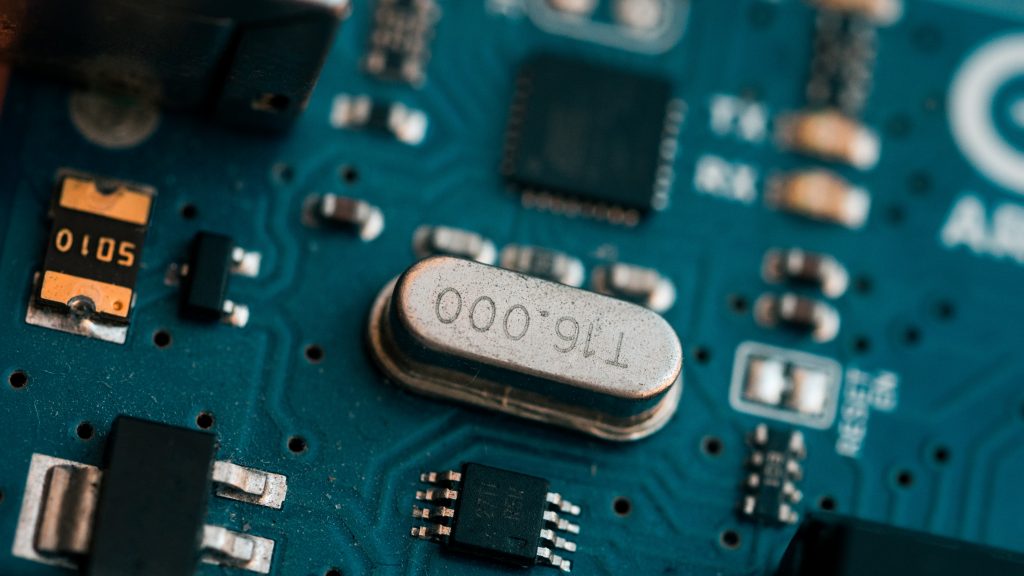
Multiple measurement setups are possible. What is important to note at the beginning of this discussion is how not to measure it. Do not measure it by probing the crystal or load capacitors directly. No matter how low capacitance your probe is (most likely it has at least 0.5pF of capacitance, possibly up to 10 times more), this will add a load capacitance to the crystal and influence the oscillation frequency.
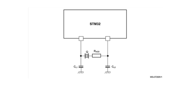
What you can always do (but involves a firmware intervention) – configure a digital output pin to output the oscillator frequency and measure it with a frequency counter. Some MCUs have digital “master clockout” pins that can be configured to directly output the oscillator frequency (for example STM32s). If you don’t have this possibility, you can configure the digital pin as the timer output (and configure the timer to use oscillator as the input). Frequency counters are devices that easily have the accuracy of ±1 ppm or even better.
If you prefer HW-only approach, you can use EMI near field probe (use one for E-field) and a spectrum analyzer. Simply locate a near field probe near the crystal while it oscillates (you might still need the FW to initialize the oscillator). Spectrum analyzers also have a frequency accuracy typically in the range of ±1 ppm. Just make sure you use a resolution bandwidth (RBW) filter of approximately 10-100Hz so you can achieve a fine resolution to determine the frequency (start with wider RBW and frequency span, locate the measured frequency on the center of the span and gradually decrease both span and RBW).
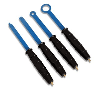
Near field probe has a negligible influence on the crystal loading. An example of near field probes set can be seen in the figure below.